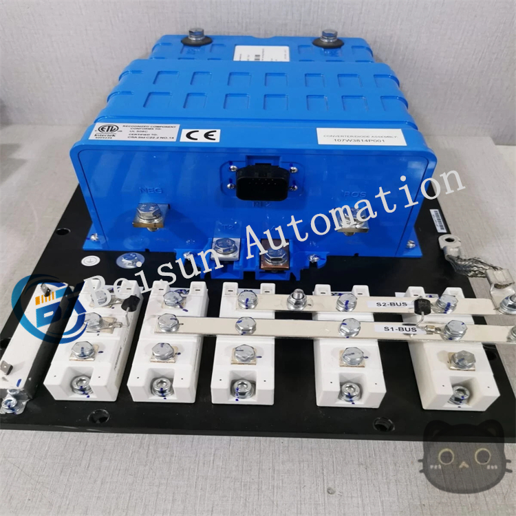
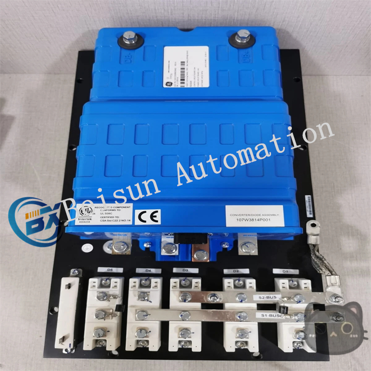
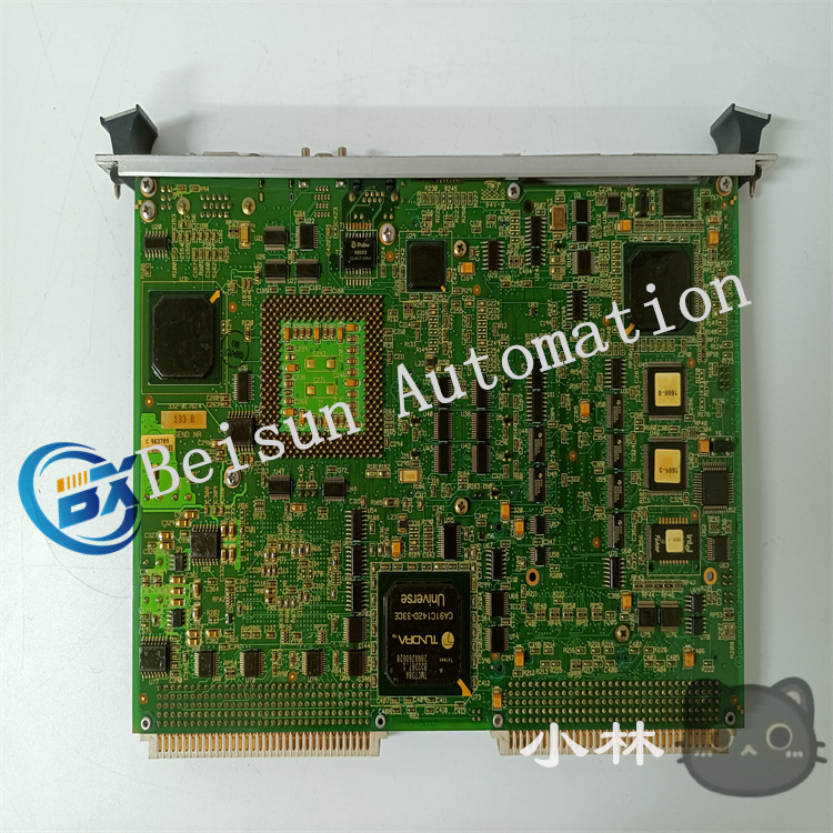
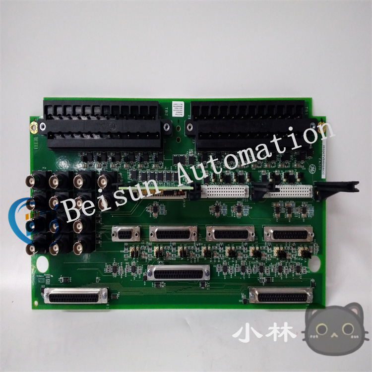
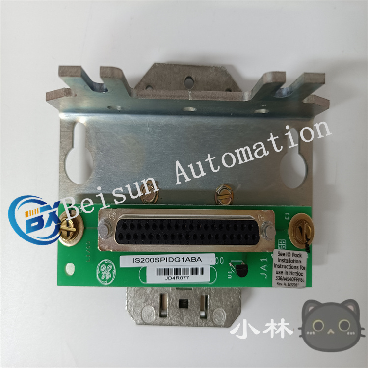
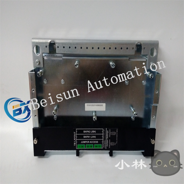
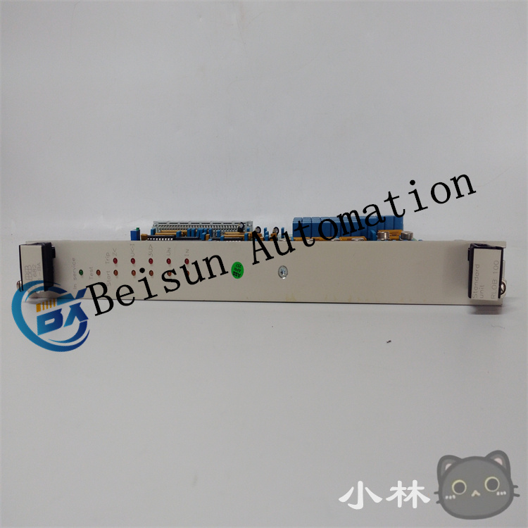
GE 151X1233DB02SA02 Digital Input Module
The working principle of the GE 151X1233DB02SA02 digital input module is based on the collaborative operation of signal acquisition, electrical isolation, level conversion, and status transmission. Its core is to convert the switching signals of external devices (such as the on-off status of sensors and buttons) into logic signals (0/1 status) recognizable by controllers like PLCs, while ensuring the safety and anti-interference performance of signal transmission. The specific working principle is as follows:
- External Signal Access: Receiving Switching Signals
The core function of the module is to receive digital signals (i.e., “0” or “1” switching status) from external devices, which usually come from:
- Mechanical contacts (such as limit switches, buttons, relay contacts);
- Electronic sensors (such as transistor output signals of photoelectric switches and proximity switches).
Signals are connected through the input terminals of the module, with a common input voltage of DC 24V (the mainstream in the industrial automation field), that is:
- When an external device is turned on (e.g., the switch is closed), there is a 24V voltage between the input terminals, which is regarded as a “high level” (logic 1);
- When the external device is turned off (e.g., the switch is open), there is no voltage or the voltage between the input terminals is lower than the threshold, which is regarded as a “low level” (logic 0).
2. Electrical Isolation: Protecting the Module and System Safety
To prevent interference (such as voltage fluctuations, surges) or faults (such as short circuits) in external circuits from affecting the internal circuits of the module and the PLC system, the module adopts photoelectric isolation technology, which is a core protection mechanism:
- After an external signal is accessed, it is first converted into an optical signal through a light-emitting diode (LED);
- The optical signal is transmitted to the phototransistor inside the module through an isolation layer (such as transparent insulating material) and then converted back into an electrical signal;
- The isolation layer completely cuts off the electrical connection between the external circuit and the internal circuit, and only transmits information through optical signals, effectively preventing problems such as common-mode interference and ground loops, and avoiding damage to the PLC motherboard by external high voltage.
-
3. Signal Conditioning: Filtering and Level Conversion
External signals may have “glitches” due to mechanical contact jitter, electromagnetic interference, etc. (such as transient on-off fluctuations at the moment the switch is closed). The module needs to process the signals through a signal conditioning circuit before outputting stable signals:
-
Filtering processing:
A built-in RC filter circuit or digital filtering logic is used to filter out high-frequency interference signals (such as electromagnetic noise) and transient signals generated by contact jitter, ensuring that only continuous and stable signals are identified (the filtering time can be set according to requirements, usually in milliseconds).
-
Level conversion:
The voltage range of the signal after isolation and filtering may not match the internal logic circuit of the module (such as TTL level). It is necessary to convert the signal into a standard level recognizable by the internal circuit (such as 5V TTL signal) through a level conversion circuit (such as a triode, dedicated chip).
-
4. Status Recognition and Transmission: Feedback Signals to the Controller
The conditioned signal is recognized as a clear “0” or “1” status by the internal logic circuit of the module, and then transmitted to controllers such as PLCs in the following ways:
- The digital status is transmitted through the internal bus between the module and the controller (such as the backplane bus of the GE Fanuc 90-30 series);
- The controller reads the status register of the module to obtain the input signals of each channel (e.g., channel 1 is 1, channel 2 is 0, etc.), which serves as the basis for logic control (such as triggering motor startup, alarm output, etc.).
5. Indicator Lights and Diagnostics: Real-Time Feedback of Working Status
Each input channel of the module is usually equipped with an LED indicator to visually display the signal status:
- When the channel receives a valid “1” signal, the indicator light is on;
- When the signal is “0” or the channel is faulty, the indicator light is off.
This design facilitates on-site engineers to quickly troubleshoot problems such as wiring errors and signal loss.
6. Protection Mechanisms: Error Prevention and Anti-Interference
To improve reliability, the module usually includes multiple protection functions:
- Overcurrent protection: A current-limiting resistor is connected in series in the input circuit to prevent damage to the module by excessive current in case of external short circuits;
- Reverse connection protection: Prevents circuit burnout caused by reverse connection of the positive and negative poles of the external power supply;
- Electromagnetic interference (EMI) resistance: Resists electromagnetic radiation interference in industrial environments through designs such as shielding layers and filter capacitors.
Summary: Overview of the Working Process
External digital signal → Access through input terminals → Photoelectric isolation (cutting off electrical connection) → Filtering and level conversion (removing interference, unifying levels) → Recognition as 0/1 status by internal logic → Transmission to the controller through the bus → Real-time status display by indicator lights.
Through this process, the module realizes the safe and stable acquisition and transmission of external switching signals, and is a key bridge connecting field devices and the control core in industrial automation systems.

Reviews
There are no reviews yet.