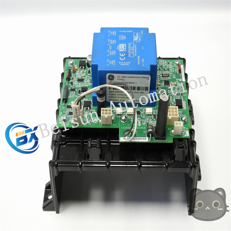
GE 151X1233DD01SA01R7 Component Board Module
As a core component responsible for battery charging control in industrial equipment, the battery charger sub-assembly board may cause problems such as abnormal charging and equipment shutdown if it malfunctions. The following are common fault types, possible causes, and corresponding solutions for reference:
I. Failure to charge or no response during charging
Fault phenomenon:
After connecting to the power supply, there is no charging current in the battery, and the indicator light does not light up or there is no response at all.
Possible causes and solutions:
-
Abnormal power input
Check whether the external power supply is normal (e.g., whether 220V/380V AC is connected, and whether the fuse is blown).
Solution: Replace the blown fuse, repair the power supply line fault, and ensure the stability of the input voltage.
-
Fault in rectifier/filter circuit
Damage to the rectifier bridge (diodes or thyristors), bulging or leakage of filter capacitors, resulting in failure to convert AC to DC.
Solution: Use a multimeter to check the conductivity of rectifier components, and replace the damaged rectifier bridge or capacitor.
-
Failure of control chip or drive circuit
Damage to the main control MCU (such as a single-chip microcomputer) or drive IC (such as a MOS tube drive chip), making it unable to send charging control signals.
Solution: Check whether the power supply voltage of the chip is normal, and replace the failed chip or drive components.
II. Excessively large or small charging current
Fault phenomenon:
The charging current is much higher than the rated value (which may cause the battery to overheat), or the current is too small (resulting in slow charging or even failure to fully charge).
Possible causes and solutions:
-
Fault in current detection circuit
Damage to the current sampling resistor (shunt), drift of the operational amplifier (used to amplify current signals), leading to misjudgment of the current value by the main control chip.
Solution: Replace the sampling resistor with abnormal accuracy, calibrate or replace the operational amplifier chip.
-
Abnormality of power devices
Aging or damage to power devices such as MOS tubes and IGBTs in the charging circuit, resulting in excessive on-resistance (small current) or short circuit (large current).
Solution: Detect the on-voltage drop of power devices, and replace the damaged MOS tubes/IGBTs and supporting heat sinks.
-
Incorrect charging parameter settings
Loss or error of parameters such as equalizing charge/float charge voltage and current threshold in the main control chip (e.g., due to EEPROM failure).
Solution: Rewrite standard parameters through a programmer or replace the memory chip.
III. Frequent interruption or automatic stop during charging
Fault phenomenon:
Charging stops suddenly after a period of time, or the indicator light flashes frequently (fault prompt).
Possible causes and solutions:
-
False triggering of overvoltage/overcurrent protection
Fault in the comparator or reference voltage source (such as TL431) in the protection circuit, leading to misjudgment of excessive voltage/current.
Solution: Check whether the protection threshold meets the design value, and replace the abnormal comparator or reference source.
-
Activation of temperature protection
Damage to the battery or circuit board temperature sensor (such as NTC thermistor), causing false reporting of high temperature; or excessive actual temperature due to poor heat dissipation.
Solution: Replace the failed temperature sensor, clean the dust on the heat sink, and check whether the fan works normally.
-
Abnormal battery detection
Poor contact of the battery interface, open circuit of the detection line, leading the main control chip to misjudge “battery not connected” or “battery damaged”.
Solution: Clean the oxide layer on the battery interface, and repair the broken line or cold solder joint of the detection line.
IV. Abnormal indicator light (not lighting, always on, or flashing randomly)
Fault phenomenon:
Status indicator lights (such as power light, charging light, fault light) display irregularly, inconsistent with the actual working status.
Possible causes and solutions:
-
Fault in indicator light drive circuit
Burnout of the indicator light current-limiting resistor, damage to the LED bulb, or failure of the drive triode (such as 8050).
Solution: Replace the damaged resistor, LED, or triode.
-
Abnormal output signal of the main control chip
Cold solder joint of the indicator light control pin of the chip, damage to the internal circuit, resulting in failure to output correct switching signals.
Solution: Resolder the pins; if the problem persists, replace the main control chip.
Summary
Troubleshooting of the battery charger sub-assembly board needs to be combined with circuit principles (such as power conversion, signal detection, and control logic). Use tools such as multimeters and oscilloscopes to detect voltage and current signals at key nodes, locate damaged components, and then replace them. Due to the high reliability requirements of industrial equipment, it is recommended to replace with original accessories of the same model to avoid secondary faults caused by parameter mismatch.
Reviews
There are no reviews yet.